
Figure 1: An active (fan cooled) heat sink used for the processor cooling in the consumer PC market. To its right is a smaller pin fin heat sink used to cool the Northbridge of the PC motherboard.
A heat sink is a term for a component or assembly that transfers heat generated within a solid material to a fluid medium, such as air or a liquid. Examples of heat sinks are the heat exchangers used in refrigeration and air conditioning systems and the radiator (also a heat exchanger) in a car. Heat sinks also help to cool electronic and optoelectronic devices, such as higher-power lasers and light emitting diodes (LEDs).
A heat sink uses its extended surfaces to increase the surface area in contact with the cooling fluid, the air for example. The term is not meant literally, as a heat sink does not have a "magical ability to absorb heat like a sponge and send it off to a parallel universe"[1]. Heat transfer theory helps explain practical aspects of how heat sinks work, and can also help to clear up common misconceptions and design mistakes. Approach air velocity, choice of material, fin (or other protrusion) design and surface treatment are some of the design factors which influence the thermal resistance, i.e. thermal performance, of a heat sink. One engineering application of heat sinks is in the thermal management of electronics, often computer CPU or graphics processors. For these, heat sink attachment methods and thermal interface materials also influence the eventual junction or die temperature of the processor(s). Theoretical, experimental and numerical methods can be used to determine a heat sink's thermal performance.
Basic heat sink heat transfer principle[]
A heat sink is an object that transfers thermal energy from a higher temperature to a lower temperature fluid medium. The fluid medium is frequently air, but can also be water or in the case of heat exchangers, refrigerants and oil. If the fluid medium is water, the 'heat sink' is frequently called a cold plate.
To understand the principle of a heat sink, consider Fourier's law of heat conduction. Joseph Fourier was a French mathematician who made important contributions to the analytical treatment of heat conduction, as published in [2]. Fourier's law of heat conduction, simplified to a one-dimensional form in the x-direction, shows that when there is a temperature gradient in a body, heat will be transferred from the higher temperature region to the lower temperature region. The rate at which heat is transferred by conduction, , is proportional to the product of the temperature gradient and the cross-sectional area through which heat is transferred.


Figure 2: Sketch of a heat sink in a duct used to calculate the governing equations from conservation of energy and Newton’s law of cooling.
Consider a heat sink in a duct, where air flows through the duct, as shown in Figure 2. It is assumed that the heat sink base is higher in temperature than the air. Applying the conservation of energy, for steady-state conditions, and Newton’s law of cooling to the temperature nodes shown in Figure 2 gives the following set of equations.
- (1)

- (2)

where (3)

Using the mean air temperature is an assumption that is valid for relatively short heat sinks. When compact heat exchangers are calculated, the logarithmic mean air temperature is used. is the air mass flow rate in kg/s.

The above equations show that
- When the air flow through the heat sink decreases, this results in an increase in the average air temperature. This in turn increases the heat sink base temperature. And additionally, the thermal resistance of the heat sink will also increase. The net result is a higher heat sink base temperature.
- The increase in heat sink thermal resistance with decrease in flow rate will be shown in later in this article.
- The inlet air temperature relates strongly with the heat sink base temperature. For example, if there is recirculation of air in a product, the inlet air temperature is not the ambient air temperature. The inlet air temperature of the heat sink is therefore higher, which also results in a higher heat sink base temperature.
- Therefore, if there is no air or fluid flow around the heat sink, the energy dissipated to the air can not be transferred to the ambient air. Therefore, the heat sink functions poorly.
- Furthermore, a heat sink is not a device with the "magical ability to absorb heat like a sponge and send it off to a parallel universe"[1].
Other examples of situations in which a heat sink has impaired efficiency:
- Pin fins have a lot of surface area, but the pins are so close together that air has a hard time flowing though them.
- Aligning a heat sink so that the fins are not in the direction of flow.
- Aligning the fins horizontally for a natural convection heat sink. Whilst a heat sink is stationary and there are no centrifugal forces and artificial gravity, air that is warmer than the ambient temperature always flows upward, given essentially-still-air surroundings; this is convective cooling.
Design factors which influence the thermal performance of a heat sink[]
Material[]
The most common heat sink material is aluminium[3]. Chemically pure aluminium is not used in the manufacture of heat sink, but rather aluminium alloys. Aluminium alloy 1050A has one of the higher thermal conductivity values at 229 W/m•K[4]. However, it is not recommended for machining, since it is relatively soft material. Aluminium alloys 6061 and 6063 are the more commonly used aluminium alloys, with thermal conductivity values of 166 and 201 W/m•K, respectively. The aforementioned values are dependent on the temper of the alloy.
Copper is also used since it has around twice the conductivity of aluminium, but is three times as heavy as aluminium[3]. Copper is also around four to six times more expensive as aluminium[3], but this is market dependent. Copper and aluminium prices can be compared in figures 3 and 4, or on Internet websites, such as the London Metal Exchange[5]. Aluminium has the added advantage that it is able to be extruded, while copper can not. Copper heat sinks are machined and skived. Another method of manufacture is to solder the fins into the heat sink base.
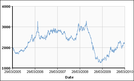 Figure 3: Aluminium cash buyer prices listed in US Dollar per metric tonne[5]. Prices are shown for the period 29 March 2005 to the 29 March 2010. |
  Figure 4: Copper cash buyer prices listed in US Dollar per metric tonne[5]. Prices are shown for the period 29 March 2005 to the 29 March 2010. |
Another heat sink material that can be used are diamonds. With a value of 2000 W/mK it exceeds that of copper by a factor of five[6]. In contrast to metals, where heat is conducted by electrons, lattice vibrations are responsible for diamond's high thermal conductivity. For thermal management applications, the outstanding thermal conductivity and diffusivity of diamond is an essential. Nowadays CVD diamond is used as submounts for high-power integrated circuits and laser diodes.
Fin efficiency[]
Fin efficiency is one of the parameters which makes a higher thermal conductivity material important. A fin of a heat sink may be considered to be a flat plate with heat flowing in one end and being dissipated into the surrounding fluid as it travels to the other[7]. As heat flows through the fin, the combination of the thermal resistance of the heat sink impeding the flow and the heat lost due to convection, the temperature of the fin and, therefore, the heat transfer to the fluid, will decrease from the base to the end of the fin. This factor is called the fin efficiency and is defined as the actual heat transferred by the fin, divided by the heat transfer, if the fin has a uniform temperature. The equations for the fin efficiency have been given before, but are repeated below. Equations 6 and 7 are applicable for straight fins.
- [8] (6)

- [8] (7)

To improve the fin efficiency of fins:
- Increase the fin thickness
- Increase the thermal conductivity of the fins
Spreading resistance[]
Another parameter that concerns the thermal conductivity of the heat sink material is spreading resistance. Spreading resistance occurs when thermal energy is transferred from a small area to a larger area in a substance with finite thermal conductivity. In a heat sink, this means that heat does not distribute uniformly through the heat sink base. The spreading resistance phenomenon is shown by how the heat travels from the heat source location and causes a large temperature gradient between the heat source and the edges of the heat sink. This means that the fins are at a lower temperature than if the heat source were uniform across the base of the heat sink. This nonuniformity increases the heat sink's effective thermal resistance.
To decrease the spreading resistance in the base of a heat sink:
- Increase the base thickness
- Choose a different material with better thermal conductivity
- Use a vapour chamber in the heat sink base.
Fin arrangements[]
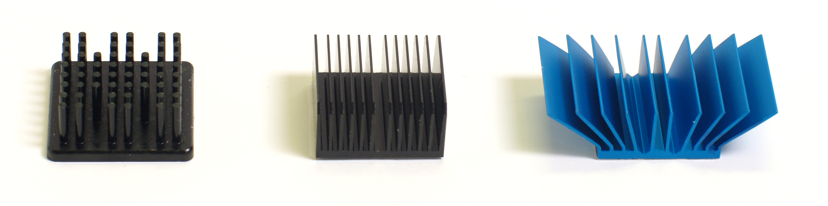

Figure 5: A pin fin, straight fin and flared heat sink types
A pin fin heat sink is a heat sink that has pins that extend from its base. The pins can be cylindrical, elliptical or square. A pin is by far one of the more common heat sink types available on the market. A second type of heat sink fin arrangement is the straight fin. These run the entire length of the heat sink. A variation on the straight fin heat sink is a cross cut heat sink. A straight fin heat sink is cut at regular intervals but at a coarser pitch than a pin fin type.
In general, the more surface area a heat sink has, the better it works[1]. However, this is not always true. The concept of a pin fin heat sink is to try to pack as much surface area into a given volume as possible[1]. As well, it works well in any orientation. Kordyan [1] has compared the performance of a pin fin and a straight fin heat sink of similar dimensions. Although the pin fin has 30 in2 surface area while the straight fin has 9 in2, the temperature difference between the heat sink base and the ambient air for the pin fin is 50°C. For the straight fin it was 44°C or 6°C better than the pin fin. Pin fin heat sink performance is significantly better than straight fins when used in their intended application where air flow is "impinged" staight on rather than through the pins.
| Heat sink fin type | Width [in] | Length [in] | Height [in] | Surface area [in²] | Volume [in³] | Temperature difference, Tcase-air [°C] |
| Straight | 1 | 1 | 1.25 | 9 | 1.25 | 44 |
| Pin | 1.5 | 1.5 | 0.65 | 30 | 1.4625 | 51 |
Another configuration is the flared fin heat sink; its fins are not parallel to each other, as shown in figure 5. Flaring the fins decreases flow resistance and makes more air go through the heat sink fin channel; otherwise, more air would bypass the fins. Slanting them keeps the overall dimensions the same, but offers longer fins. Forghan, et al.[9] have published data on tests conducted on pin fin, straight fin and flared fin heat sinks. They found that for low approach air velocity, typically around 1 m/s, the thermal performance is at least 20% better than straight fin heat sinks. Lasance and Eggink [10] also found that for the bypass configurations that they tested, the flared heat sink performed better than the other heat sinks tested.
Engineering applications[]
Processor/Microprocessor cooling[]
Heat dissipation is an unavoidable by-product of all but micropower electronic devices and circuits [7]. In general, the temperature of the device or component will depend on the thermal resistance from the component to the environment, and the heat dissipated by the component. To ensure that the component temperature does not overheat, a thermal engineer seeks to find an efficient heat transfer path from the device to the environment. The heat transfer path may be from the component to a printed circuit board (PCB), to a heat sink, to air flow provided by a fan, but in all instances, eventually to the environment.
Two additional design factors also influence the thermal/mechanical performance of the thermal design:
- The method by which the heat sink is mounted on a component or processor. This will be discussed under the section attachment methods.
- For each interface between two objects in contact with each other, there will be a temperature drop across the interface. For such composite systems, the temperature drop across the interface may be appreciable [8]. This temperature change may be attributed to what is known as the thermal contact resistance [8]. Thermal interface materials (TIM) decrease the thermal contact resistance.
Attachment methods for microprocessors and similar ICs[]
As power dissipation of components increases and component package size decreases, thermal engineers must innovative to ensure components won't overheat. Devices that run cooler last longer. A heat sink design must fulfill both its thermal as well as its mechanical requirements. Concerning the latter, the component must remain in thermal contact with its heat sink with reasonable shock and vibration. The heat sink could be the copper foil of a circuit board, or else a separate heat sink mounted onto the component or circuit board. Attachment methods include thermally conductive tape or epoxy, wire-form z clips, flat spring clips, standoff spacers, and push pins with ends that expand after installing.
- Thermally conductive tape
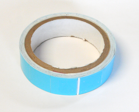

Figure 6: Roll of thermally conductive tape.
Thermally conductive tape is one of the most cost-effective heat sink attachment materials[11]. It is suitable for low-mass heat sinks and for components with low power dissipation. It consists of a thermally conductive carrier material with a pressure-sensitive adhesive on each side.
This tape is applied to the base of the heat sink, which is then attached to the component. Following are factors that influence the performance of thermal tape[11]:
- Surfaces of both the component and heat sink must be clean, with no residue such as a film of silicone grease.
- Preload pressure is essential to ensure good contact. Insufficient pressure results in areas of non-contact with trapped air, and results in higher-than-expected interface thermal resistance.
- Thicker tapes tend to provide better "wettability" with uneven component surfaces. "Wettability" is a term used to describe the percentage area of contact of a tape on a component. Thicker tapes, however, have a higher thermal resistance than thinner tapes. From a design standpoint, it is best to strike a balance by selecting a tape thickness that provides maximum "wettablilty" with minimum thermal resistance.
- Epoxy
Epoxy is more expensive than tape, but provides a greater mechanical bond between the heat sink and component, as well as improved thermal conductivity[11]. The epoxy chosen must be formulated for this purpose. Most epoxies are two-part liquid formulations that must be thoroughly mixed before being applied to the heat sink, and before the heat sink is placed on the component. The epoxy is then cured for a specified time, which can vary from 2 hours to 48 hours. Faster cure time can be achieved at higher temperatures. The surfaces to which the epoxy is applied must be clean and free of any residue.
The epoxy bond between the heat sink and component is semi-permanent/permanent[11]. This makes re-work very difficult and at times impossible. The most typical damage caused by rework is the separation of the component die heat spreader from its package.


Figure 7: A pin fin heat sink with a z-clip retainer.
- Wire form Z-clips
More expensive than tape and epoxy, wire form z-clips attach heat sinks mechanically. To use the z-clips,the printed circuit board must have anchors. Anchors can be either soldered onto the board, or pushed through. Either type requires holes to be designed into the board. The use of RoHS solder must be allowed for because such solder is mechanically weaker than traditional Pb/Sn solder.
To assemble with a z-clip, attach one side of it to one of the anchors. Deflect the spring until the other side of the clip can be placed in the other anchor. The deflection develops a spring load on the component, which maintains very good contact. In addition to the mechanical attachment that the z-clip provides, it also permits using higher-performance thermal interface materials, such as phase change types[11].


Figure 8: Two heat sink attachment methods, namely the maxiGRIP (left) and Talon Clip
- Clips
Available for processors, clips attach directly to ball grid array components. The clips make use of the gap created by the ball grid array (BGA) between the component underside and PCB top surface. The clips therefore require no holes in the PCB. They also allow for easy rework of components. Examples of commercially available clips are the maxiGRIPTM and superGRIPTM range from Advanced Thermal Solutions (ATS) and the Talon ClipTM from Malico. The three aforementioned clipping methods use plastic frames for the clips, but the ATS designs uses metal spring clips to provide the compression force. The Malico design uses the plastic "arm" to provide a mechanical load on the component. Depending on the product requirement, the clipping methods will have to meet shock and vibration standards, such as Telecordia GR-63-CORE, ETSI 300 019 and MIL-STD-810.


Figure 9: Push pins.
- Push pins with compression springs
For larger heat sinks and higher preloads, push pins with compression springs are very effective[11]. The push pins, typically made of brass or plastic, have a flexible barb at the end that engages with a hole in the PCB; once installed, the barb retains the pin. The compression spring holds the assembly together and maintains contact between the heat sink and component. Care is needed in selection of push pin size. Too high an insertion force can result in the die cracking and consequent component failure.
- Threaded standoffs with compression springs
For very large heat sinks, there is no substitute for the threaded standoff and compression spring attachment method [11]. A threaded standoff is essentially a hollow metal tube with internal threads. One end is secured with a screw through a hole in the PCB. The other end accepts a screw which compresses the spring, completing the assembly. A typical heat sink assembly uses two to four standoffs, which tends to make this the most costly heat sink attachment design. Another disadvantage is the need for holes in the PCB.
| Method | Pros | Cons | Cost |
| Thermal tape | Easy to attach. Inexpensive. | Cannot provide mechanical attachment for heavier heat sinks or for high vibration environments. Surface must be cleaned for optimal adhesion. Moderate to low thermal conductivity. | $ |
| Epoxy | Strong mechanical adhesion. Relatively inexpensive. | Makes board rework difficult since it can damage component. Surface must be cleaned for optimal adhesion. | $$ |
| Wire form Z-clips | Strong mechanical attachment. Easy removal/rework. Applies a preload to the thermal interface material, improving thermal performance. | Requires holes in the board or solder anchors. More expensive than tape or epoxy. Custom designs. | $$$ |
| Clip-on | Applies a preload to the thermal interface material, improving thermal performance. Requires no holes or anchors. Easy removal/rework. | Must have "keep out" zone around the BGA for the clip. Extra assembly steps. | $$$ |
| Push pin with compression springs | Strong mechanical attachment. Highest thermal interface material preload. Easy removal and installation. | Requires holes in the board which increases complexity of traces in PCB. | $$$$ |
| Stand-offs with compression springs | Strongest mechanical attachment. Highest preload for the thermal interface material. Ideal for large heat sinks. | Requires holes in the board which increases complexity of trace layout. Complicated assembly. | $$$$$ |
Thermal interface materials[]
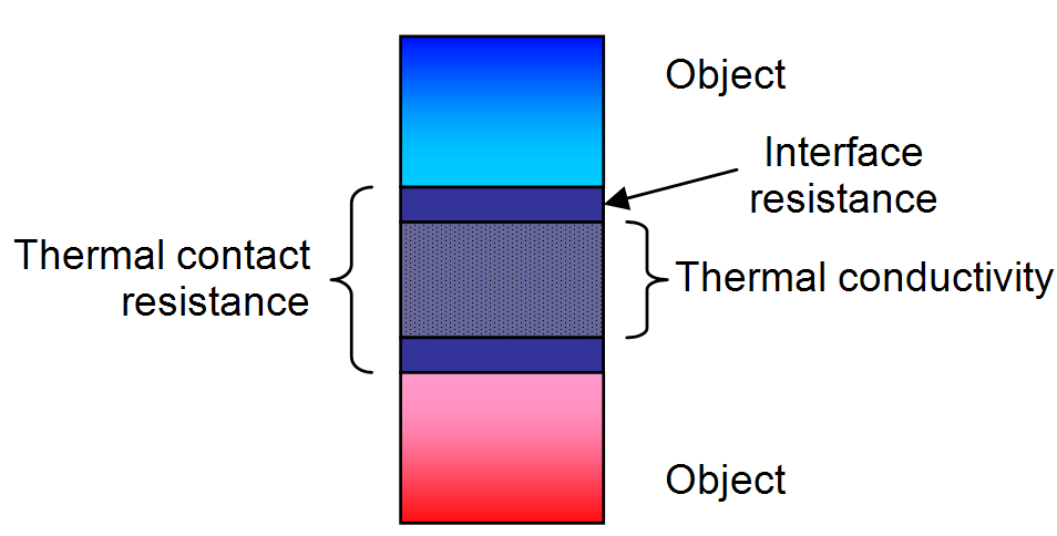

Figure 10: Thermal conductivity and the interface resistance form part of the thermal interface resistance of an thermal interface material.
Thermal contact resistance occurs due to the voids created by surface roughness effects, defects and misalignment of the interface. The voids present in the interface are filled with air. Heat transfer is therefore due to conduction across the actual contact area and to conduction (or natural convection) and radiation across the gaps [8]. If the contact area is small, as it is for rough surfaces, the major contribution to the resistance is made by the gaps [8]. To decrease the thermal contact resistance, the surface roughness can be decreased while the interface pressure is increased. However, these improving methods are not always practical or possible for electronic equipment. Thermal interface materials (TIM) are a common way to overcome these limitations,
Properly applied thermal interface materials displace the air that is present in the gaps between the two objects with a material that has a much-higher thermal conductivity. Air has a thermal conductivity of 0.022 W/m•K [12] while TIMs have conductivities of 0.3 W/m•K [13] and higher.
When selecting a TIM, care must be taken with the values supplied by the manufacturer. Most manufacturers give a value for the thermal conductivity of a material. However, the thermal conductivity does not take into account the interface resistances. Therefore, if a TIM has a high thermal conductivity, it does not necessarily mean that the interface resistance will be low.
Selection of a TIM is based on three parameters: the interface gap which the TIM must fill, the contact pressure, and the electrical resistivity of the TIM. The contact pressure is the pressure applied to the interface between the two materials. The selection does not include the cost of the material. Electrical resistivity may, or may not, be important, depending upon electrical design details.
| Interface gap values | Products types available |
| < 2 mil | Thermal grease, epoxy, phase change materials |
| 2 – 5 mil | Phase change materials, polyimide, graphite or aluminium tapes |
| 5 – 18 mil | Silicone coated fabrics |
| > 18 mil | Gap fillers |
| Contact pressure scale | Typical pressure ranges | Product types available |
| Very low | < 70 kPa | Gap fillers |
| Low | < 140 kPa | Thermal grease, epoxy, polyimide, graphite or aluminium tapes |
| High | 2 MPa | Silicone coated fabrics |
| Electrical insulation | Dielectric strength | Typical values | Product types available |
| Not required | N/A | N/A | Thermal grease, epoxy, phase change materials, graphite or aluminium tapes. |
| Required | Low | < 300 V/mil | Silicone coated fabrics, gap fillers |
| Required | High | > 1500 V/mil | Polyimide tape |
| Product type | Application notes | Thermal performance |
| Thermal paste | Messy. Labour intensive. Relatively long assembly time. | ++++ |
| Epoxy | Creates ‘permanent’ interface bond. | ++++ |
| Phase change | Allows for pre-attachment. Softens and conforms to interface defects at operational temperatures. Can be repositioned in field. | ++++ |
| Thermal tapes, including graphite, polyimide, and aluminium tapes | Easy to apply. Some mechanical strength. | +++ |
| Silicone coated fabrics | Provide cushioning and sealing while still allowing heat transfer. | + |
| Gap filler | Can be used to thermally couple differing-height components to a heat spreader or heat sink. Naturally tacky. | ++ |


Figure 11: High power LEDs from Philips Lumileds Lighting Company mounted on 21 mm star shaped metal-core PCBs
Light emitting diode lamps[]
Light emitting diode (LED) performance and lifetime are strong functions of their temperature[14]. Effective cooling is therefore essential. A case study of a LED based downlighter shows an example of the calculations done in order to calculate the required heat sink necessary for the effective cooling of lighting system[15]. The article also shows that in order to get confidence in the results, multiple independent solutions are required that give similar results. Specifically, results of the experimental, numerical and theoretical methods should all be within 10% of each other to give high confidence in the results.
Firestopping and fireproofing[]
| This article needs additional citations for verification. Please help improve this article by adding reliable references. Unsourced material may be challenged and removed. (January 2010) |


Figure 12: Fire test where the steel pipe penetrant to absorb and conduct heat from the furnace, through to the unexposed side.
A heat sink is rarely a desired thing in passive fire protection. Rather, it is usually a problem that must be overcome to maintain fire-resistance ratings. The proven ability to overcome heat sinks in construction is subject to building code and fire code regulations.
Firestopping[]
- Problem – Metallic penetrants and sleeves, at a density of 7.9 kg/L are denser than common firestops or concrete. Consequently, during a fire, they will absorb more heat and conduct it to the unexposed side of a fire barrier (thus "cooling" the exposed side at the expense of the unexposed side), such as the cold side of a firewall. This is undesirable. Even if the fire is stopped by the barrier, one must keep the unexposed side cool to prevent autoignition of combustibles on the unexposed side of a fire barrier. The unexposed side may very well be an area of refuge, which must be safeguarded to comply with the building code. Greater penetrant and sleeve conductivity leads to lower T-ratings. Higher density firestops, such as firestop mortars act as heat sinks to absorb heat away from small penetrants, such as cables, thus increasing T-ratings.
- Benefit – a rare exception where heat sinks are beneficial in firestops is where intumescents must be activated, such as in a firestop containing a plastic pipe. Heat sinks such as wire mesh and extra metallic sleeving may be used to carry heat to intumescents to activate expansion which should choke off a melting plastic pipe or melting pipe covering, such as foamed plastic or fibreglass.
Fireproofing[]
In fireproofing of structural steel as well as providing circuit integrity to cables, cable trays, junction boxes and electrical conduit, the metallic items that are protected by the fireproofing measures act as heat sinks. Fireproofing methods are used to defeat the heat sink properties of the items they protect. In the case of circuit integrity measures, electrical services will fuse and short circuit above 140°C.
In soldering[]
Temporary heat sinks were sometimes used while soldering circuit boards, preventing excessive heat from damaging sensitive nearby electronics. In the simplest case, this means partially gripping a component using a heavy metal crocodile clip, hemostat or similar clamp. Modern semiconductor devices, which are designed to be assembled by reflow soldering, can usually tolerate soldering temperatures without damage. On the other hand, electrical components such as magnetic reed switches can malfunction if exposed to hotter soldering irons, so this practice is still very much in use [16].
Methods to determine heat sink thermal performance[]
In general, a heat sink performance is a function of material thermal conductivity, dimensions, fin type, heat transfer coefficient, air flow rate, duct size. To determine the thermal performance of a heat sink, a theoretical model can be made. Alternatively, the thermal performance can be measured experimentally. Due to the complex nature of the highly 3D flow in present in applications, numerical methods or CFD can also be used. This section will discuss the aforementioned methods for the determination of the heat sink thermal performance.
A heat transfer theoretical model[]
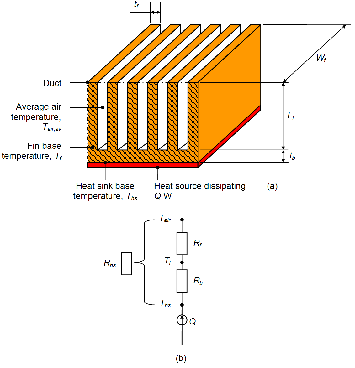

Figure 13: Sketch of a heat sink with equivalent thermal resistances.
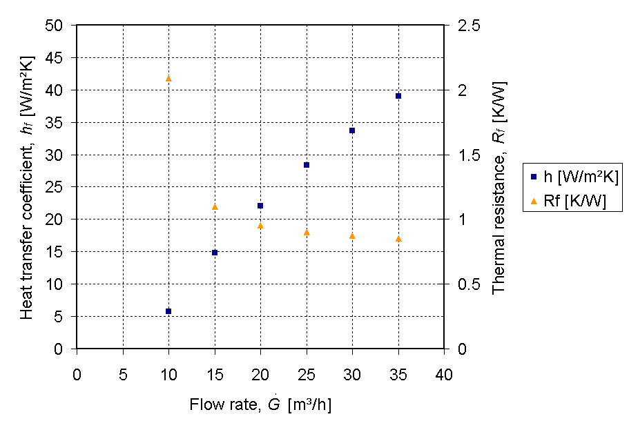

Figure 14: Thermal resistance and heat transfer coefficient plotted against flow rate for the specific heat sink design used in [17]. The data was generated using the equations provided in the article. The data shows that for an increasing air flow rate, the thermal resistance of the heat sink decreases.
One of the methods to determine the performance of a heat sink is to use heat transfer and fluid dynamics theory. One such method has been published by Jeggels, et al.[17], though this work is limited to ducted flow. Ducted flow is where the air is forced to flow through a channel which fits tightly over the heat sink. This makes sure that all the air goes through the channels formed by the fins of the heat sink. When the air flow is not ducted, a certain percentage of air flow will bypass the heat sink. Flow bypass was found to increase with increasing fin density and clearance, while remaining relatively insensitive to inlet duct velocity [18].
The heat sink thermal resistance model consists of two resistances, namely the resistance in the heat sink base, , and the resistance in the fins, . The heat sink base thermal resistance, , can be written as follows if the source is a uniformly applied the heat sink base. If it is not, then the base resistance is primarily spreading resistance:


- (4)

where is the heat sink base thickness, is the heat sink material thermal conductivity and is the area of the heat sink base.


The thermal resistance from the base of the fins to the air, , can be calculated by the following formulas.
- (5)

- [8] (6)

- [8] (7)
- (8)

- (9)

- [19] (10)

- [19] (11)

- (12)

- (13)

The flow rate can be determined by the intersection of the heat sink system curve and the fan curve. The heat sink system curve can be calculated by the flow resistance of the channels and inlet and outlet losses as done in standard fluid mechanics text books, such as Potter, et al.[20] and White [21].
Once the heat sink base and fin resistances are known, then the heat sink thermal resistance, can be calculated as:

(14)

Using the equations 5 to 13 and the dimensional data in [17], the thermal resistance for the fins was calculated for various air flow rates. The data for the thermal resistance and heat transfer coefficient are shown in Figure 14. It shows that shows that for an increasing air flow rate, the thermal resistance of the heat sink decreases.
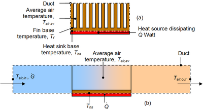
Figure 15: Sketch of a heat sink in a duct used to calculate the governing equations from conservation of energy and Newton’s law of cooling.
Experimental methods[]
Experimental tests are one of the more popular ways to determine the heat sink thermal performance. In order to determine the heat sink thermal resistance, the flow rate, input power, inlet air temperature and heat sink base temperature need to be known, as shown in figure 15. However, figure 15 shows a test setup for a ducted flow heat sink application. Vendor-supplied data is commonly provided for ducted test results[22]. However, the results are optimistic and can give misleading data when heat sinks are used in an unducted application. Another problem with the set up, be it unducted or ducted, is the losses into the board. These must be taken into account. More details on heat sink testing methods and common oversights can be found in Azar, et al.[22].
Numerical methods[]
In industry, thermal analyses are often ignored in the design process or performed too late — when design changes are limited and become too costly[7]. Of the three methods mentioned in this article, theoretical and numerical methods can be used to determine an estimate of the heat sink or component temperatures of products before a physical model has been made. A theoretical model is normally used as an first order estimate. Numerical methods or computational fluid dynamics (CFD) provide a qualitative (and sometimes even quantitative) prediction of fluid flows[23].What this means is that it will give a visual or post-processed result of a simulation, like the images in figures 16 and 17, but the quantitative or absolute accuracy of the result is not guaranteed.
CFD can give an insight into flow patterns that are difficult, expensive or impossible to study using experimental methods[23]. Experiments can give a quantitative description of flow phenomena using measurements for one quantity at a time, at a limited number of points and time instances. If a full scale model is not available or not practical, scale models or dummy models can be used. The experiments can have a limited range of problems and operating conditions. Simulations can give a prediction of flow phenomena using CFD software for all desired quantities, with high resolution in space and time and virtually any problem and realistic operating conditions. However, the results still need to be validated. Another problem with CFD is that the inputs need to be correct. It is the classic case of "Garbage in, garbage out."[1]


.jpg)
References[]
- ↑ 1.0 1.1 1.2 1.3 1.4 1.5 1.6 Kordyban, T., 1998, Hot air rises and heat sinks – Everything you know about cooling electronics is wrong, ASME Press, NY.
- ↑ Fourier, J. B., 1822, Theorie analytique de la chaleur, Paris; Freeman, A., 1955, translation, Dover Publications, Inc, NY.
- ↑ 3.0 3.1 3.2 Anon, Unknown, "Heat sink selection", Mechanical engineering department, San Jose State University [27 January 2010].
- ↑ "Aluminium Matter Organization UK"
- ↑ 5.0 5.1 5.2 "London Metal Exchange"
- ↑ Fareed, M., "Diamond: Thermal properties" [4 April 2010]
- ↑ 7.0 7.1 7.2 Sergent, J. and Krum, A., 1998, Thermal management handbook for electronic assemblies, First Edition, McGraw-Hill.
- ↑ 8.0 8.1 8.2 8.3 8.4 8.5 8.6 8.7 Incropera, F.P. and DeWitt, D.P., 1985, Introduction to heat transfer, John Wiley and sons, NY.
- ↑ Forghan, F., Goldthwaite, D., Ulinski, M., Metghalchi, M., 2001, Experimental and Theoretical Investigation of Thermal Performance of Heat Sinks, ISME May.
- ↑ Lasance, C.J.M and Eggink, H.J., 2001, A Method to Rank Heat Sinks in Practice: The Heat Sink Performance Tester, 21st IEEE SEMI-THERM Symposium.
- ↑ 11.0 11.1 11.2 11.3 11.4 11.5 11.6 11.7 Azar, K, et al., 2008, "Heat sink attachment options – What are they and what do you need to know about them?", Qpedia Thermal Management E-Magazine, July
- ↑ Lienard, J.H., IV & V, 2004, A Heat Transfer Textbook, Third edition, MIT
- ↑ 13.0 13.1 13.2 13.3 Saint-Gobain, 2004, "Thermal management solutions for electronic equipment" 22 July 2008
- ↑ Bider, C, 2009, "Effect of thermal environment on LED light emission and lifetime", LED Professional Review May/June 2009.
- ↑ Azar, K., et al., 2009, "LED lighting: A case study in thermal management", Qpedia Thermal E-Magazine, September, 2009.
- ↑ James Johnston, "Reed Switches", Electronics in Meccano, Issue 6, January 2000.
- ↑ 17.0 17.1 17.2 Jeggels, Y.U., Dobson, R.T., Jeggels, D.H., Comparison of the cooling performance between heat pipe and aluminium conductors for electronic equipment enclosures, Proceedings of the 14th International Heat Pipe Conference, Florianópolis, Brazil, 2007.
- ↑ Prstic, S., Iyengar, M., and Bar-Cohen, A., 2000, Bypass effect in high performance heat sinks, Proceedings of the International Thermal Science Seminar Bled, Slovenia, June 11 – 14.
- ↑ 19.0 19.1 Mills, A.F., 1999, Heat transfer, Second edition, Prentice Hall.
- ↑ Potter, C.M. and Wiggert, D.C., 2002, Mechanics of fluid, Third Edition, Brooks/Cole.
- ↑ White, F.M., 1999, Fluid mechanics, Fourth edition, McGraw-Hill International.
- ↑ 22.0 22.1 Azar, A, et al., 2009, "Heat sink testing methods and common oversights", Qpedia Thermal E-Magazine, January 2009 Issue [24 March 2010].
- ↑ 23.0 23.1 Kuzmin, D., Unknown, "Course: Introduction to CFD", Dortmund University of Technology.
See also[]
- Computer cooling
- Heat spreader
- Heat pipe
- Heat pump
- Radiator
- Thermal management of electronic devices and systems
- Thermal resistance in electronics
da:Køleplade de:Kühlkörper es:Disipador fr:Dissipateur thermique ko:히트 싱크 it:Dissipatore (elettronica) he:צלעות קירור lt:Radiatorius (elektronikoje) nl:Koelvin ja:ヒートシンク pl:Radiator pt:Dissipador de calor ru:Кулер simple:Heat sink sk:Chladič (elektronika) fi:Jäähdytyssiili sv:Kylfläns th:ฮีตซิงก์ zh:散热片